Key Terms
- Resistor network
- Resistors in parallel
- Resistors in series
Objectives
- Identify principles for analyzing circuits with more than one resistor
- Analyze simple circuits with two resistors in parallel or in series
We will look more closely at these types of circuits and learn some principles that will allow you to analyze other complex resistor circuits. Circuits with more than one resistor are sometimes called resistor networks.
Resistors in Parallel
For the sake of brevity, we will only look at two-resistor circuits (networks). This leaves us two basic arrangements: resistors in parallel and resistors in series. A circuit with two resistors in parallel is shown below. The resistors R1 and R2 may or may not have the same resistance.

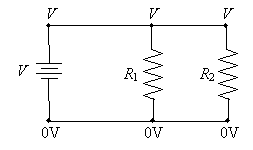
Thus, we can see that the voltage across each resistor in parallel is the same--in this case, the voltage V. Note, however, that because of Ohm's law, the current through each resistor is different: it depends on the resistance R of the resistor.
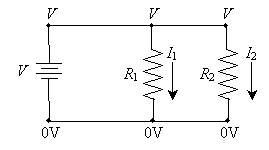

The currents through the resistors are the following (again, simply applying Ohm's law):


 and
and 
Remember that positive current flows from the positive terminal of the power supply toward the negative terminal. The power supply must provide both I1 and I2 simultaneously. We can see logically that the power supply must therefore provide the sum of the two currents; this total splits (something like a river with two branches), with part of the current (I1) going through resistor R1 and the other part of the current (I2) going through resistor R2.
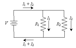

Thus, we can draw another important conclusion about circuit analysis: the current entering any particular point of the circuit must generally be the same as the current leaving that point. (There are some exceptions to this rule, but they are beyond the scope of this article.) Note that this is particularly applicable to points A and B marked below.
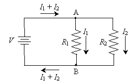

For instance, the total current entering point A (I1 + I2) is equal to the total current leaving the point (the sum of I1 and I2).
Practice Problem: What is the current through resistor R2 in the circuit below?

Solution: We know from our discussion that the voltage drop across resistors in parallel is the same. In this configuration, that voltage is 3V. We can then simply use Ohm's law to calculate the current through R2.


Thus, 0.3 amperes of current flows through R2.
Resistors in Series
The other potential arrangement of two resistors in a simple circuit is called resistors in series. This arrangement is shown in the circuit diagram below.
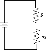
We can analyze this circuit using the principles we have discussed thus far. First, we know that the total voltage drop across the two resistors (i.e., from point A to point B) is the same as the voltage across the terminals of the power supply (which we'll call V).
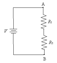

We also noted above that the current entering any particular point must be the same as the current leaving that point. As a result of this principle, the current through resistor R1 must be the same as the current through resistor R2. We'll call this current I. The diagram below replaces points A and B with the corresponding voltages at those points (relative to ground). We've also added an unknown voltage Vm (m for middle) to represent the voltage on the wire connecting the two resistors.
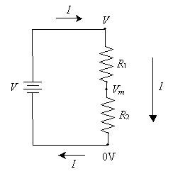

Using Ohm's law, we can determine the voltage drop across both R1 and R2. This process requires a little algebra, but we can derive a general formula for calculating Vm. First, We know that the voltage drop across R1 is the difference between V and Vm (or V - Vm). By Ohm's law, this is equal to the product of I and R1.


And the voltage drop across R2 is Vm (or Vm - 0 = Vm). Again using Ohm's law, this voltage drop is the product of I and R2.

Here, we must solve these two equations simultaneously, first by eliminating I. (If you're not that familiar with algebra, don't worry--simply note that we can come up with an equation for Vm that always works for this circuit.)


Now, let's solve for Vm. We assume here that V, R1,and R2 are known.


This latter expression allows us to calculate the voltage across the second resistor, R2.
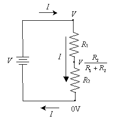

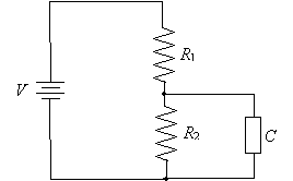
Using this result, we can determine the current in the circuit and the voltage drop across each resistor if we just know the power supply voltage V and the resistances R1 and R2. Incidentally, this circuit is sometimes called a voltage divider because the voltage across the second resistor is less than the power-supply voltage. This characteristic is key to providing lower voltages to certain portions of a more complex circuit--say, if we attached another electronic component in parallel with R2. This circuit is slightly more complex than simply two resistors in series or in parallel, but you can see that we can apply some of the same concepts to realize that the general component C (which may or may not be a resistor) has the same voltage drop as resistor R2, which is less than the supply voltage V.
Practice Problem: A simple circuit with two resistors in series has a supply voltage of 10V. The first resistor has a resistance of 2? and the second a resistance of 8?. What is the power dissipated by the second resistor?
Solution: First, let's draw a circuit diagram and label the components appropriately.
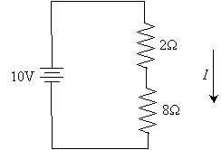
To calculate the power dissipated by the second (8?) resistor, we first need to find the current I. To do so, let's calculate the voltage drop across the second resistor using the formula we derived earlier. We'll call this voltage drop Vm, following the above convention.
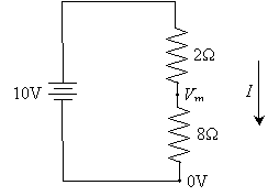


Now, let's use Ohm's law to determine I.


Now, using the current through the resistor (1 ampere) and the voltage drop across it (8 volts), we can calculate the power dissipated by it.


Thus, the resistor dissipates 8 watts. Note that it is pure coincidence that the voltage, power, and resistance of the resistor all have the same numerical value (8). This will not always be the case.


