Key Terms
- Resistor
- Perfect conductor
- Resistance
- Ohm's law
- Voltage drop
- Power dissipation
Objectives
- Define resistance and the role of resistors in electrical circuits
- Use Ohm's law to relate voltage, current, and resistance
- Determine how much heat is produced in a resistor relative to its voltage and current
Placing a conductor (a wire, for instance) across the terminals of a battery (a type of power supply) will quickly deplete the stored energy. But what if we place some object or device in the circuit that "resists" the current flow? That is, we want to use the electrical potential energy to do some kind of useful work. Such a device is called a resistor because it resists or impedes the flow of current through the circuit.
Please note: do not attempt to replicate the diagrams, illustrations, or instructions in this article in a real-life scenario. Doing so may result in electric shock, injury, or death. These examples are provided only for theoretical discussion and not for actual/physical use.
Perfect Conductors
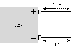
Before we discuss resistors, however, we first need to introduce a caveat regarding the conductors (wires) we use in our circuit models. Specifically, we will assume that they are perfect conductors: they do not in any way resist or impede the flow of charge. We can therefore logically deduce that the voltage at any point in a continuous conductor relative to ground is the same, regardless of its shape or length. By convention and for simplicity, we'll generally say that ground is 0V (just as we might say the physical ground around us is measured as 0 meters). Thus, in the case of the 1.5V battery shown below, everywhere on the top wire is at 1.5V relative to ground, and everywhere on the bottom wire is 0V.
Resistor Circuits
A simple resistor circuit simply involves connecting a resistor across the terminals of the power supply. The circuit symbol for a resistor is shown below.

And the following is a simple resistor circuit.

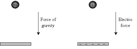
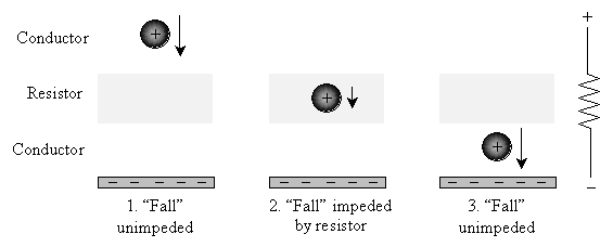
Now, let's seek to understand what's happening in a resistor circuit by comparison to gravity. Recall that charge being moved by an electric force is very similar to mass being moved by a gravitational force.
But what if we introduce a layer of water or some other liquid that the mass must fall through? That liquid will slow the ball down compared with its (relatively) unimpeded fall through air (or, even better, its completely unimpeded fall through a vacuum). When the ball falls through this liquid layer, some of its gravitational potential energy is converted to heat energy. (The same phenomenon is responsible for the burning and glowing of meteors that hit the Earth's atmosphere at a high speed.)
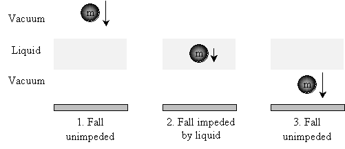
Because some of the gravitational potential energy is converted to heat by way of friction ("rubbing"--when you rub your hands together, for example, they get warmer), the ball does not reach the ground with the same energy of motion that it would have had in the absence of the liquid layer.
A resistor circuit is almost exactly analogous to this situation. Instead of a vacuum and a liquid, we have a conductor and a resistor. In a (perfect) conductor, charge flows freely, and its movement is unimpeded. In a resistor, however, the flow of charge is impeded, resulting in the creation of heat as charged particles (electrons) "bump" into atoms, causing them to slow down. The result is that some of the electrical potential energy is converted to heat.
Ohm's Law
The extent to which the resistor impedes the flow of charge is a parameter called resistance, which is often expressed as R. Recall that we said a higher voltage generally produces a higher current through a circuit. Conversely, a higher resistance generally reduces the amount of current through a circuit more than a lower resistance. We can thus define the resistance of a circuit as the ratio of voltage to current in that resistor. Writing this mathematically, where the current is expressed as I and the voltage as V,

Rearranging this equation slightly gives us the familiar form of Ohm's law.

The units of resistance are ohms (written as ?). One ohm is the same as one joule-second per square coulomb (don't ask what that means!).
Now, let's return to our resistor circuit. We noted that the voltage is constant on each wire (which we're modeling as perfect conductors--in reality, wires have some resistance, but it's negligible for our purposes). Thus, the voltage across our resistor in this case is the same as the voltage across the power supply.
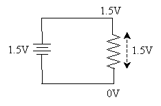
Because charge loses potential energy as it flows through a resistor, the voltage across that resistor is called a voltage drop.
Practice Problem: How much current flows through the resistor R in the circuit below?

Solution: We need to use Ohm's law to calculate the current (I) using the information provided in the circuit diagram.
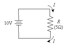
First, we know that the power supply voltage (V) is 10 volts, and the resistance of the resistor (R) is 5 ohms. Below is the form of Ohm's law that we must use.

Plugging in the numbers and calculating the results yields the answer.

The current flowing in the circuit is 2 amperes.
Power Dissipation
Recall from the above discussion that when charge flows through a resistor, it loses potential energy by way of heat. Thus, when you connect an incandescent light bulb to a power supply (either a fixture such as a lamp or batteries in a flashlight), the filament in the bulb (nothing but a wire resistor) heats until it glows, creating light. As it turns out, the amount of potential energy converted to heat--also called power dissipation--is simply the product of the voltage (V) and current (I) "in" the resistor. Let's call this power dissipation P.

If we analyze the units, we find that power dissipation is expressed as joules per second, which we also call a watt. Thus, for example, a 100-watt light bulb converts 100 joules per second of potential energy into heat, causing the filament in the bulb to glow and illuminate its surroundings. Alternatively, by performing some algebraic manipulation of this expression combined with Ohm's law, power is also equivalent to the product of the resistance and the square of the current.

For our purposes, both of these equations are legitimate means of calculating the power dissipated by a resistor R.
Practice Problem: The two (non-ground) terminals in a typical electrical socket have a voltage of 120V across them. If you connect a 30W light bulb to this socket, how much current is flowing through the circuit?
Solution: This problem requires us to first diagram the circuit and then use what we know about electronics to find the current flowing in the bulb (or circuit). Let's model the electrical socket using our power supply symbol. Because the light bulb is nothing more than a resistor, we'll use our resistor symbol.
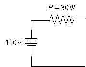
Note that the resistor is positioned slightly differently in the circuit compared with our previous examples. This makes no physical difference, because the voltages on the wires (which we are calling perfect conductors) are the same everywhere. Thus, the voltage drop across the resistor is still 120V.
Now, let's use the power equation to calculate the current through the 30W bulb.


Thus, a quarter amp (0.25 amps) flows through the bulb.


