It probably goes without saying that the whole reason you create drawings in Visio 2013 is to either print them or share them with other people. That means that knowing how to properly print or share the diagrams and flowcharts you create will be just as important as knowing how to create them.
In this article, we'll discover how to:
-
Print diagrams and flowcharts
-
Remove personal information from documents
-
Create graphics, including JPEG and GIF
-
Save drawings in formats other than Visio
-
Share diagrams using Visio Viewer
-
Publish Visio diagrams to the Internet as a web page
Printing in Visio 2013
When you're finished with a drawing or just ready to print a copy, click on the File tab, then click Print on the left hand side of the window in Backstage view.
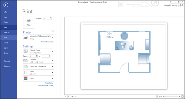
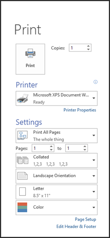
You will see your print options to the right of the blue column.
To the right of your print options, you'll see the preview pane.
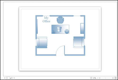
Only the active page will appear in the preview pane. You can switch to another page by clicking an arrow at the bottom left.

You can also use zoom at the bottom right of the page to zoom in or out.

Now let's cover print options.
First, select the number of copies that you want to print.
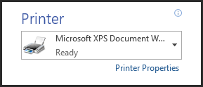
Select the printer you want to use to print your drawing.
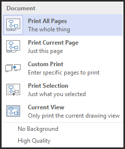
Choose if you want to print all pages, a range of pages, etc.
Select if you want the pages collated.
Next, decide the orientation you want to use for printing, either landscape or portrait.
Choose the size of paper you'll use to print, then if you want to print in color or in black and white.
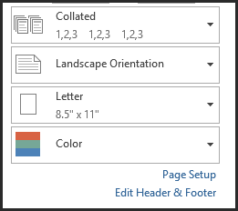
Click the blue Page Setup link (shown in the snapshot above).
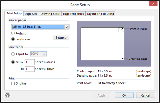
In the dialogue box pictured above, you can see the print setup options.
You can also make changes to the page size, drawing scale, page properties, and layout & routing.
All of the options in these tabs should be self-explanatory except for Drawing Scale.
Now, go back to the print options by closing out the dialogue box.
Click the Edit Header & Footer link.
You will then see the Header and Footer dialogue box, as pictured below.
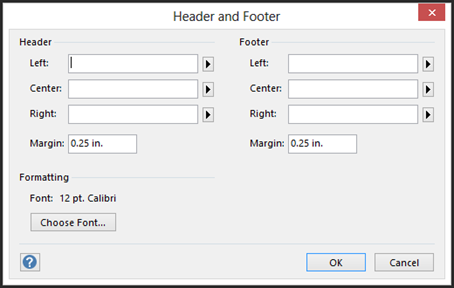
You can add or edit a header or footer in this box, as well as choose the font for the header or footer.
You can align your header and/or footer to the left, center, or right of the page. You can also specify margins.
Remember, headers appear at the top of your drawings. Footers appear at the bottom.
Removing Personal Information
There may be some personal information contained in the metadata of your document. This personal information may include your name, and this may be information you don't want permanently attached to your drawing.
To remove personal information, click the File tab, then click Info on the left.
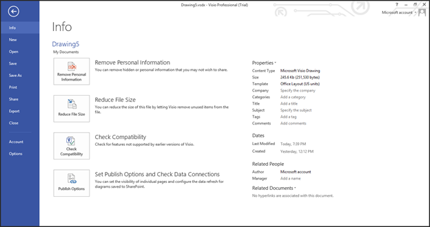
Click the Remove Personal Information button.
This will open the Remove Hidden Information dialogue box.
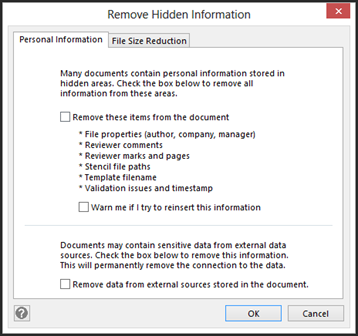
Click the OK button after you're finished.
Creating Graphics
In the next section, we're going to learn about saving your Visio 2013 drawings. You'll have several file formats to choose from when you save drawings. However, you can also turn your drawings into graphics, such as a JPEG image.
Just as when you save your drawing, Visio 2013 offers you several graphics formats.
These formats are:
-
BMP or DIB � Windows Bitmap
-
EMG � Enhanced Metafile
-
EMZ � Compressed Enhanced Metafile
-
GIF � Graphic Interchange Format
-
JPEG � Joint Photographic Experts Group
-
PNG � Portable Network Graphic
-
SVG � Scalable Vector Graphics
-
SVG � Scalable Vector Graphics Compressed
-
TIF � Tag Image File Format
-
WMF � Windows Metafile
To do turn a drawing into a graphic, go to File>Export.
Click Change File Type.
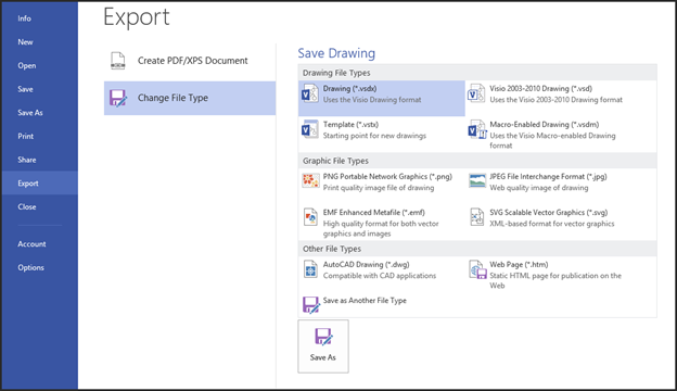
We are going to choose JPEG under Graphic File Types.
Click the Save As button.
Choose the location where you want to save the image, then click Save.
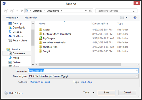
Select your output options.
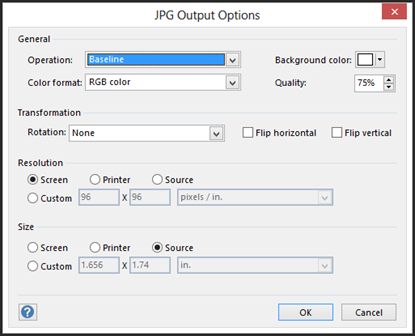
Click OK.
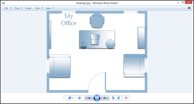
You can now view your graphic with any photo editor or viewer, as shown below.
Saving a Drawing in Other Formats
The Visio 2013 default format is .vsdx. However, you can save your document in several other formats, including Auto Cad Drawing (.dwg) and a web page (.html).
To save your drawing in another format, go to File>Save As.
Enter a name for the file in the File Name field.
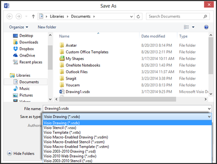
In the Save as Type field, choose the format you want to use to save the file.
Click the Save button when you're finished.
Sharing Diagrams with Visio Viewer
The Visio Viewer is a way that anyone can view your Visio drawings, whether they have Visio installed or not. If the viewer has Visio, the drawing will open in the Visio program. If they do not have Visio installed on their machine, the drawing will open in Internet Explorer.
Let's look at how it works on a machine that doesn't have Visio installed.
Double click on the file in Windows Explorer.
You might see a warning asking you if the webpage has permission to run the add-on "Microsoft Visio Viewer" from Microsoft Corporation.
Click the Allow button.

You will then see a security warning that looks like this:

Click the Run button.
The Visio drawing then appears in Internet Explorer. To make the drawing easier to view, there will be zoom controls, as well as page navigation controls. In addition, there will be three buttons to give control over display, layer, and markup information.
Publishing Visio Diagrams on the Internet
Your Visio 2013 drawing can be turned into a website to share with others, if you want it to be. Visio will generate a website for that you that includes foreground pages and hyperlinks. It will also have a table of contents, as well as pan-and-zoom for easy navigation.
To take advantage of this feature, go to File>Export>Change File Type.
Double click on Web Page (.htm).
You'll then see the Save As dialogue box.
Click Save.
You will then see the progress as Visio converts your drawing to a web page.
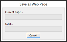
When it is finished converting your drawing, a window will open in Internet Explorer.
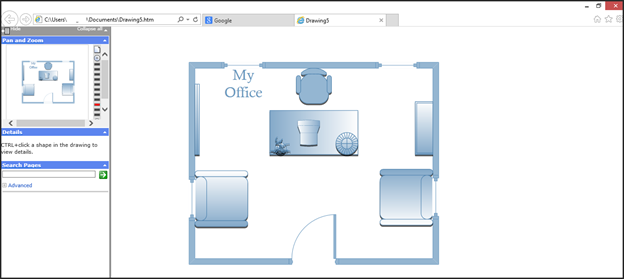
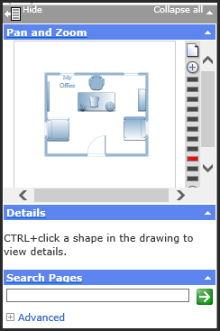
Notice the navigation pane on the left side of the window (shown below). From this pane, you can pan-and-zoom, get details about any shape in the drawing, or search the pages.
Creating Network and Rack Diagrams
We're going to learn how to:
-
Create a network diagram
-
Organize network shapes in a diagram
-
Create a rack diagram
-
Add equipment to a rack diagram
-
Set and modify drawing scales
Creating a Basic Network Diagram
Both versions of Visio contain a basic network diagram template. The professional version contains a detailed network diagram in addition to the basic; however, you can learn all you need to know by creating the basic version. In truth, the biggest difference between the basic and detailed network diagram templates is the detailed network diagram offers more stencils.
To create a basic network diagram, go to File>Open. Go to the Network category and open the Basic Network Diagram template.
Take a minute to notice the stencils in the Shape window.
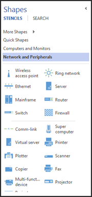
To get started, place an Ethernet shape on the drawing page. You should place it so it's in the vertical center of the page. The Ethernet shape is located in the Network and Peripherals stencil.
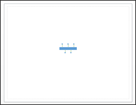
Now, resize the shape by dragging on a side handle so that the shape is four inches long. Use the rulers for the measurement.
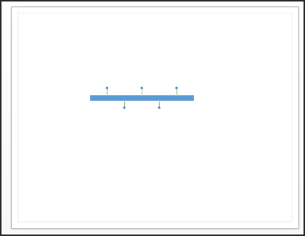
The width bar located on the Status bar shows you the current length too. You can use that as a guide.

Label the Ethernet Shape "Store 1."

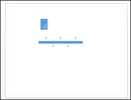
Next, drag a Server shape on the page. Place it over the Ethernet shape and to the left, as shown below.
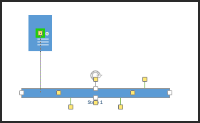
Select the Ethernet shape. Drag a yellow control handle toward the center of the server, as shown below.
Place a Printer shape above and to the right of the Ethernet shape, then three PC shapes (Computer and Monitors stencil) below the Ethernet shape.
Connect the Ethernet shapes to the shapes you added.
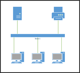
Next, drag a bounding box around all the shapes. Drag and move them to toward the bottom left of the page.
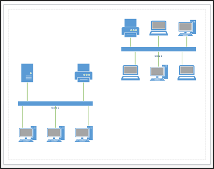
In the upper right side of the page, drag another Ethernet shape.
Drag a size handle to make it the same size as the first Ethernet shape. A green arrow will appear beneath it when it reaches the same width, as shown below.

Label this shape "Store 2".
Place a printer shape, two laptop computers, and three computers so it looks like the snapshot below:
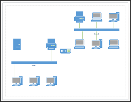
Place a router in the center of the page.
Connect each of the Ethernet shapes to the router.
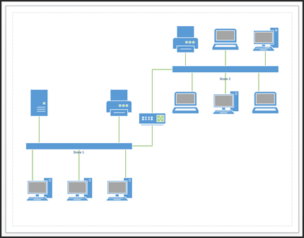
And that's all there is to it! As you can see, creating a basic network diagram isn't difficult at all. Now you can add data to the shapes or link data to the diagram if you wish.
Organizing Network Shapes
Now that you have created your network diagram, you may want to organize the shapes. We're going to teach you how in this section by teaching you to add a background shape, then grouping the shapes in the network.
Let's start by right clicking on the page.
In the mini toolbar that appears, click the dropdown arrow for Drawing Tools, as shown below.

We are going to use the rectangle tool to draw a rectangle around the first network we created.
However, the rectangle is blocking our view of the network.
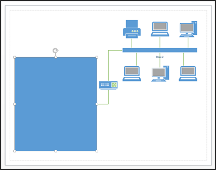
That is because it is in front of the network. We want it to appear as a background behind the network.
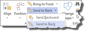
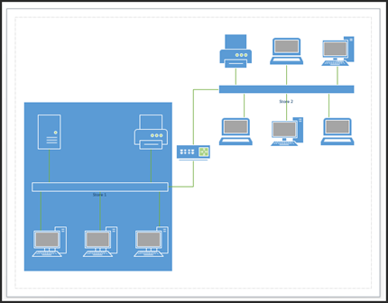
To fix this, go to Home>Send to Back.
It's still a little too dark, so we're going to change that now.
We're going to select the shape, right click, and choose Format Shape.
The Format Shape pane opens on the right side of the window. This should look familiar to you.
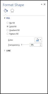
Click the triangle beside Fill.
Adjust the transparency.
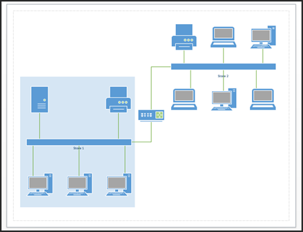 .
.
Next, we're going to group the shapes. However, if you don't remember, drag a bounding box around the rectangle and all the shapes.
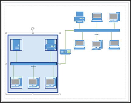
Go to Home>Group>Group.
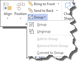
You can now follow the same steps with the network labeled "Store 2."
Creating a Rack Diagram
A rack, by definition, is a metal frame that holds devices such as servers, hard disk drives, modems, and etc. It looks like a shelf where components can be stacked on top of each other, then screwed into the front. A rack diagram, in turn, is a drawing of a computer rack that you can then add equipment (shapes in Visio) to.
Let's learn to create a rack diagram, then add the equipment to it.
To start with, let's go to File>New, then choose the Network category. Open the Rack Diagram template.
When you open this template, you'll notice that it contains four stencils. Three of the four stencils contain equipment and rack shapes.
Click the Rack Mounted Equipment stencil in the Shapes window.
Go to the page tab at the bottom of your page in the Drawing window. Double click on the current page name. Type in Overview. Press Enter when you're finished.
Now, right click on the page name, and select Insert.
You will then see the Page Setup dialogue box.
Click on the Page Properties tab.
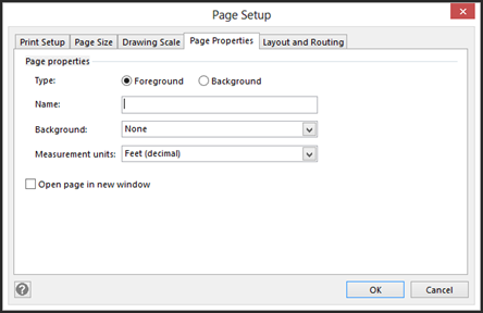
In the Name field, type a name for the new page. We've chosen Network Center.
Click on the Measurement Units dropdown and select Meters. This is the measurements used for the new page.
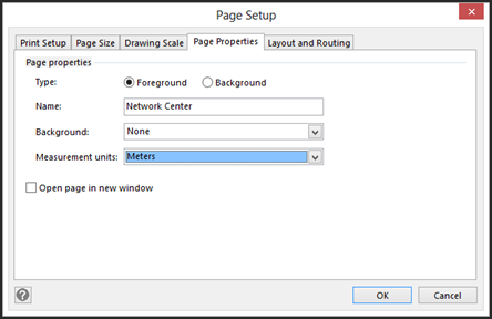
Now click on the Drawing Scale tab.
Click Pre-defined Scale.
Select Metric, then 1:10.
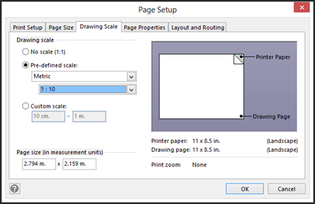
Click OK.
Next, you can drag a rack shape from the Shapes window onto your page. You've already set the measurement units and page scale. Because of this, the rack goes from the top to the bottom margin of the page.
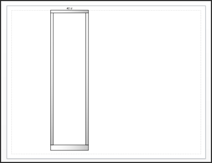
Now that you've drawn your rack, it's time to start adding equipment.
Adding Equipment to Racks
The shapes that you add to your equipment rack look 2-D, unlike the shapes we have worked with thus far. They are 1-D shapes, so you can glue the ends; they just look two dimensional. However, you'll drag them and glue them just the same.
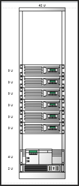
Let's drag a Power Supply and place it at the bottom of the rack.
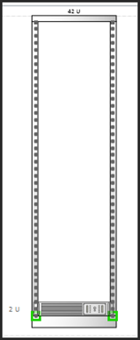
Notice that the sides of the shape can be glued to the rack. This is marked by green. Also notice that the U height appears to the left (2U). The U height is the number of rack units the component occupies.
Next, drag the Server shape and place it in center of the rack.
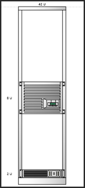
Note the default server shape of 8U. Let's resize it by dragging the handles until it's 3U.
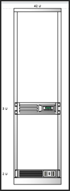
We're going to add more servers to our rack, but we want them all to be 3U. To do this, we're going to select our server, then press CTRL+D five times for five more servers.
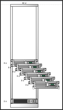
Place these above and below the current server.
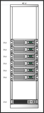
Drag a Router shape and place it above the power supply.
Place a keyboard tray above the router.
Place a shelf above the keyboard tray.
Place then a monitor (from the Freestanding Rack Equipment stencil) on top of the shelf.
Note that we had to move our servers up higher on the rack to make this happen.
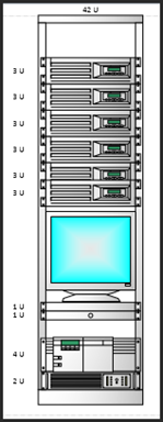
You can now go through and add shape data to the shapes in your drawing. This is an important part of creating a rack diagram because it lets you know where all your equipment is located.
About Drawing Scales
It goes without saying that it would be impossible to draw the actual size of an equipment rack on a page. However, that doesn't mean we don't want actual size representations on the page.
When we create a drawing in Visio, whether it's a rack with equipment or a floor plan for an office, we want to make sure that the shapes we add to our drawing represent actual objects AND accurately represent the amount of space they will inhabit. For example, you might have a drawing scale that's 1":1'. This means that one inch of drawing space equals one foot of actual space.
Changing the Drawing Scale
When we created the rack diagram, we changed the ratio between the drawings and the real equipment. We changed it to 1:10. In that instance, we made the change before we started to create the diagram. However, there may be times when you need to change the drawing scale after you've created the drawing.
Let's learn how to do that.
Go to the page for which you want to change the scale.
Right click on the page tab.
Select Page Setup, then choose the Drawing Scale tab.
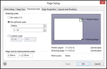
Next, select Pre-Defined Scale.
Choose a pre-defined scale or create your own scale values with a Custom Scale.
If you want to change the measurement units, go to the Page Properties tab in the same dialogue box. Go to Measurement Units and choose the unit you want to use.
Click Apply to save the changes you've made.
Validate Flowcharts and Diagrams
When you validate a flowchart or diagram, you check it against a list of rules to discover any errors. Visio 2013 will detect things like missing connectors. If connectors aren't attached to other shapes, for example, this will appear is a problem.
To validate a flowchart or diagram, go to Process>Check Diagram.
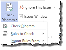
You'll see a window open with a list of possible problems.
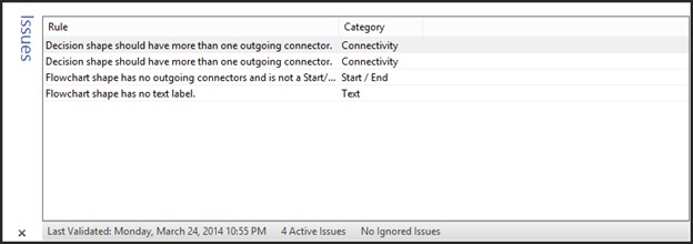
If you want to ignore an issue that Visio points out, right click on the issue and choose either Ignore This Issue or Ignore This Rule.
When you choose Ignore this Rule, Visio will then hide all issues that were caused by the rule.
Importing Validation Rules
You can import validation rules into a diagram, either from other diagrams you've created in Visio 2013 or those you created with earlier versions of Visio.
To do this, go to Process>Check Diagram>Import Rules From.
The rule sets for Flowchart and BPMN are available to any diagram. However, they're meant to be used with process diagrams. If any other diagrams that have rules are open, you'll see the file names listed.
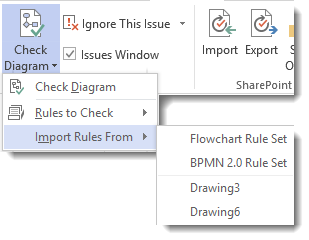
Select a rule set or open drawing.
The rules will then be imported.
Deciding Which Rules are Active
You can view which rule sets are active for a drawing by going to Process>Check Diagram>Rules to Check.
Rule sets that are active have a checkmark next to them.
To make a rule set inactive, click on the rule set to remove the checkmark.


